Two boards on 868 MHz: the Discovery kit's first ping
Last time the Discovery kit only ever said it transmitted. This time a second radio, built on different silicon and a different software stack, independently says it heard, and breaking the link on purpose shows which settings the air interface actually demands.
The last post ended on an admission. The Discovery kit told me it transmitted. The radio accepted its configuration, entered transmit mode, reported the packet done, and I believed it. But "the board says so" is not the same as "another radio heard it." No signal had been independently confirmed to leave the bench. This post closes that loop.
The goal is again deliberately small: get one other radio to hear the Discovery kit, once. Not a network. Not a range figure. One independently-witnessed packet. Raw LoRa has no handshake and no negotiation. There is no exchange where two radios agree on how to talk; a human aligns the two by hand, parameter by parameter, or they never meet.
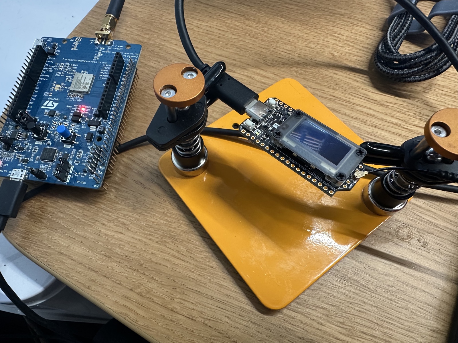
And the witness has to be a stranger. The transmitter is the same STM32 from 1.1a, firmware untouched, still beaconing BrochSignal 1.1a #N every ten seconds: STM32 + Semtech SX1276 + the arduino-LoRa library. The receiver is a different MCU, a different radio chip, a different library, from a different vendor: ESP32-S3 + Semtech SX1262 + RadioLib. That asymmetry is the whole point. If these two agree, it cannot be one ecosystem nodding along with itself.
The other board, and why it's a different animal
The receiver is a diymore "LoRa V4", which is a Heltec WiFi LoRa 32 V4 clone: ESP32-S3 plus a Semtech SX1262, EU868. I'll name it both ways once and then just call it the V4. In 1.1a I left a caveat open in the firmware comments: confirm the silkscreen actually reads V4 before trusting the pin map. It does. The board is marked HTIT-WB32LAF v4.3. One open question closed before the radio even powered on.
What makes this board worth choosing is its lineage, not its specs. The transmitter runs Semtech's first-generation SX1276 driven by a generic Arduino library. The receiver runs the second-generation SX1262 driven by RadioLib. Two chip families, two libraries, two MCUs, written by people who have never coordinated. If the V4 hears the STM32, that's the air interface itself agreeing, not a shared codebase.
The bring-up was the mirror image of last time's fight. In 1.1a the Discovery kit's onboard ST-Link refused to attach because the factory demo had dropped the STM32 into STOP mode with its debug clock gated; I had to flash under reset. The V4 has no such drama. It enumerated as /dev/cu.usbmodem2101, described by macOS as a "USB JTAG/serial debug unit", VID:PID 303A:1001: Espressif's native USB-CDC, baked into the S3 itself. No ST-Link, no CP2102 bridge, no chip between the MCU and the port. pio run -t upload just worked; no BOOT-button dance.
The build was uneventful. The one figure worth keeping: the firmware came out roughly ten times larger than the 1.1a transmitter's, because an ESP32-S3 with RadioLib pulls in a far heavier framework than a bare STM32L0 ever needs.
Three settings the receiver had to equal exactly
Three settings on the receiver had to match 1.1a exactly. RadioLib happens to get two of them right already (I set them anyway, so the match is explicit rather than luck), and it actively gets the third wrong by default.
- Sync word
0x12(the "private" network value, a one-byte tag that lets a radio ignore traffic from networks it isn't part of). RadioLib's SX126x default already is0x12, so this one matches out of the box; I set it explicitly so the link doesn't depend on a library default I didn't choose. On the SX1262 it's stored as the0x1424register pair, interoperable with the single-byte0x12the SX1276 uses. Same idea, two chip generations expressing it differently. - Preamble length 8 symbols. That's what
arduino-LoRasends by default on the other end, and also RadioLib's SX126x default on this end. Another one that matches without intervention; set explicitly for the same reason. - CRC off. This is the one RadioLib actually gets wrong. It turns the payload CRC on by default; the 1.1a firmware never enables it, so its packets carry no CRC at all. Leave RadioLib on its default and it silently rejects every single packet as corrupt: a receiver working perfectly and reporting absolutely nothing.
setCRC(false)is the one-line fix, and it's the setting most likely to leave you staring at a dead monitor while everything is, in fact, fine.
Why each of those matters is the second half of this post. First, the payoff.
The first ping
Reception was immediate. Before the log itself, three numbers ride on every received line, and it pays to know what they mean:
- RSSI (dBm): how loud the packet arrived. Always negative, and closer to zero is stronger. Pressed up against the transmitter on the bench it pins near
0.00(saturated, more on that below). Out in the field a usable link often runs -100 to -120 dBm, and past the radio's sensitivity floor (around -123 dBm at SF7, lower at higher spreading factors) the packets stop. Distance, obstructions, antenna, and transmit power all move it. - SNR (dB): how far the signal stands above the noise. Positive means louder than the noise floor, but LoRa's whole trick is decoding when it is not: SF7 still copies down to about -7.5 dB, SF12 to around -20 dB. The steady +13 dB here is huge margin. A higher spreading factor buys more of this headroom, at the cost of airtime; interference and a faint signal spend it.
- f_err (Hz): how far the incoming carrier sat from where the receiver expected it. Two oscillators never agree exactly, and this is the leftover gap; the radio pulls small ones in on the fly. Single or double-digit Hz, as here, means two well-matched references (both boards run a TCXO). Cheap crystal boards drift by kHz, and temperature nudges it around. This is drift within tolerance, not the deliberate 0.1 MHz miss from the matching game later: 0.1 MHz is 100,000 Hz, far past anything the receiver can pull back.
The moment the monitor came up, the counter was already arriving:
Broch Signal — Lesson 1.1b — raw LoRa, RX-only (the V4 listens)
radio.begin()... ok
config: 868.1 MHz  SF7  BW125  CR4/5  sync 0x12  preamble 8  CRC off
listening for "BrochSignal 1.1a #N" ...

RX #1  "BrochSignal 1.1a #1"  19 bytes   RSSI -38.00 dBm   SNR 13.25 dB   f_err 7.75 Hz
RX #2  "BrochSignal 1.1a #2"  19 bytes   RSSI -39.00 dBm   SNR 12.50 dB   f_err 7.75 Hz
RX #3  "BrochSignal 1.1a #3"  19 bytes   RSSI -36.00 dBm   SNR 7.00 dB   f_err -178.25 Hz
That RX #1 line is the packet 1.1a could only assert. The STM32 keyed the air; a separate radio, built by other people on other silicon, demodulated the bytes back into the same string. The green LED on the V4 blinked once per line, in time with the Discovery kit's own LED a metre away.
The numbers had a physical reality to them from the start. Around RX #9 I clipped a stub antenna onto the V4 and the RSSI shifted. Later, nudging the board a few centimetres on the desk moved the frequency error from roughly 7.75 Hz to roughly 23.25 Hz, with one wild outlier at -178.25 Hz on RX #3. Treat those f_err numbers with some care: RadioLib's SX126x frequency-error readout is undocumented, reverse-engineered from a sister chip, and flagged "use with caution" by its own maintainer, and that lone -178.25 Hz spike is exactly the kind of wild value it is known to throw. Indicative, not gospel. The consistent ones still make the point: two radios never sit on exactly the same frequency, you can push the gap around with a fingertip, and the SX1262 will at least estimate how wide it is.
The number I'm not allowed to be proud of
Now the caveat, and it has to land before we start breaking things, or the rest misleads. Walk the RSSI down the log: the early packets read -35 to -39 dBm, a couple spiked to -17 and -23 dBm, and then most of them pinned flat to 0.00 dBm.
0.00 dBm is not a great signal. It is the front end saturated: a +14 dBm transmitter sitting one metre away, drowning the receiver until the RSSI meter runs out of headroom and reports nothing meaningful. It says too much signal, not long reach. The trustworthy near-field figure here is the SNR, which held steady around 12.0 to 13.25 dB throughout: the modem was demodulating cleanly with plenty of margin, regardless of what the pinned RSSI claimed.
So there is no RSSI-versus-distance story in this post, and I want to say that plainly so no sentence here can be misread as range. Real range numbers don't exist until the transmitter is far enough away to stop pinning the meter. That's the forward link: Lesson 1.2, the range walk, carrying one of these boards up the hill.
The matching game: breaking it on purpose
The first ping proved the settings matched. It did not prove why each one matters, so I left the transmitter completely alone and broke exactly one receiver setting at a time: watch what fails, restore it, move to the next. The modem parameters were unforgiving, and the failures were verbatim.
Frequency. 868.1 → 868.2: just 0.1 MHz off, the monitor ran perfectly, the banner printed, and zero packets came through. A bigger jump to 878.1 was just as dead. Only the exact 868.1 worked, so a tenth of a megahertz is the line between a clean link and silence.
Spreading factor. SF7 → SF11: nothing received. This is the moment to say what a chirp actually is, because the whole air interface rests on it. LoRa sends each symbol as a tone that sweeps across the band, a chirp; the spreading factor sets how slowly that sweep climbs (higher SF is slower, more robust, and longer on air), and the bandwidth sets how wide it ranges. The receiver decodes by correlating against the exact sweep it expects, so change the SF and it is hunting for the wrong shape and hears nothing, the same way an off-frequency radio does.
Bandwidth had two distinct modes. 125.0 → 124.0 kHz still worked. RadioLib snaps to the nearest valid bandwidth, which is 125, so functionally nothing changed. But 125.0 → 120.0 kHz was a different kind of failure entirely: radio.begin() returned code -8 and the firmware HALTed. That's not silent deafness; it's the invalid value getting rejected up front by begin()'s own safety net, before the radio ever tries to listen. Worth distinguishing: one setting makes the radio quietly deaf, another makes it refuse to start.
Stops the link
- Frequency off by 0.1 MHz: monitor runs, zero packets
- Spreading factor SF7 → SF11: nothing received
- Bandwidth 120 kHz: invalid, begin() returns code -8 and HALTs
Survives
- Bandwidth 124 kHz: snapped to nearest valid (125), still works
- Coding rate 4/5 → 4/8: still received fine (see below)
Frequency, spreading factor and bandwidth are the modem parameters needed to detect and demodulate the chirp at all. They have to match before a single bit of the packet can be read.
Coding rate: the setting you don't have to match
I expected the coding rate to behave like the other three. It doesn't. I changed the receiver from 4/5 to 4/8 (LORA_CR 5 → 8) while the transmitter stayed at 4/5, and it still received fine.
The reason is the cleanest piece of LoRa internals I've met so far. A LoRa packet in explicit-header mode (the default, and what 1.1a sends) begins with a PHY header, and that header is always transmitted at the most robust 4/8 coding rate, no matter what the payload uses. The header carries three things: the payload length, the payload's coding rate, and whether a CRC is present. The receiver reads the coding rate out of each packet's header and uses that; it ignores whatever you set locally.
So coding rate rides inside the packet. Frequency, spreading factor and bandwidth are needed just to find and demodulate the packet in the first place; they're properties of the carrier, so both ends must agree in advance. Coding rate is a property of the payload, announced by the packet itself, so the receiver can simply be told. That's the dividing line the whole experiment drew: some settings the air interface demands you match by hand, and some it describes to you on arrival.
An aside: the banner that lied
One rough edge throughout the experiments. The firmware prints a config banner on boot (config: 868.1 MHz SF7 BW125 CR4/5 sync 0x12 preamble 8 CRC off), and it kept printing exactly that even after I'd edited the #defines and the radio had genuinely reconfigured. For a confusing minute I thought a setting hadn't taken, until I read my own code: that banner is a hard-coded string, not a readout of the radio's live state. It says what I once typed, not what the chip is doing.
Mildly annoying mid-experiment, but a clean little lesson, and a cousin of last post's "the board says so" scepticism: trust the instrument's live measurements over its labels. The RSSI and SNR were read off the radio each packet. The banner was a sticky note I'd left for myself.
What this bought is a real change in standing. The unverified "it transmitted" from 1.1a is now an independently-confirmed ping across two unrelated silicon stacks, plus a map of which radio settings you have to align by hand and which the packet describes for you. The negotiation LoRaWAN will later automate is, at this layer, just a person editing #defines until two radios meet.
Next the V4 talks back (the two-way ping-pong), and after that Lesson 1.2 carries one of these boards up the hill until RSSI means something. If you want your own RX #1 before then, the firmware is in the companion repo below: point any SX1262-and-RadioLib board at an SX1276 transmitter, match 868.1, SF7, BW125, sync 0x12, preamble 8, and CRC off, and a beacon should appear within seconds. If your near-field RSSI behaves differently from mine, I'd like to hear it.